History of Technical Drawings: Ancient Sketches to Digital Creativity
Table of Contents
Have you ever wondered how a Belfast engineer’s CAD file becomes the interactive 3D product viewer that wins a contract with a German manufacturer? Or how a detailed technical blueprint transforms into the LinkedIn post that generates qualified enquiries?
The journey from technical drawing to digital marketing asset mirrors the broader historical evolution of technical drawing practices, from Leonardo da Vinci’s hand-sketched flying machines to today’s AI-powered design tools. But here’s what’s changed: the precision and clarity that once required years of drafting training is now accessible to any Northern Ireland SME with the right approach.
For Belfast manufacturers, engineering firms, and professional services, this evolution presents an opportunity. Your technical drawings (those CAD files, blueprints, and schematics gathering digital dust on servers) aren’t just internal documentation. They’re marketing assets that prove expertise, build B2B trust, and communicate capability in ways that generic stock photography never could.
This article traces the fascinating history of technical drawing from ancient Egypt to the Industrial Revolution, through the CAD revolution of the 1980s, and into today’s world, where AI tools and web-based platforms democratise design capabilities. More importantly, we’ll show you how to bridge the gap between your existing technical assets and the customer-facing marketing materials that generate leads and win contracts.
Whether you’re trying to showcase precision engineering to procurement officers, demonstrate architectural vision to planning committees, or explain complex processes to international buyers, the principles remain unchanged: translate complex ideas into clear visual communication. The tools, however, have never been more accessible.
Join us as we explore the origins, advancements, and practical applications of technical drawing—an art form that continues to bridge imagination and reality.
Origins and Early History of Technical Drawing

The roots of technical drawing, also called engineering drawing, stretch deep into human history, closely tied to the progress of civilisation. Long before written language, early humans expressed ideas visually through drawings. Cave paintings, such as those found in Lascaux, France, though primarily artistic, reflect an inherent human tendency to translate thoughts into images, serving as an early precursor to technical drawing.
The Dawn of Practical Drawings
When humans began constructing tools, shelters and monuments, drawings took on a new purpose. Around 3000 BCE, the ancient Egyptians used detailed plans on papyrus and stone as essential guides for achieving accuracy in large-scale projects such as the construction of pyramids, temples, and complex irrigation networks. These early drawings were created to represent objects, such as buildings and equipment, on a flat surface, allowing for practical planning and execution.
In Mesopotamia, clay tablets inscribed with cuneiform script showcased early city grids, irrigation systems, and monumental ziggurats. These methodical artworks bridged creativity and precision, marking the first steps in recognising technical drawing as a crucial tool for problem-solving and future planning.
Mathematical Approaches and Descriptive Geometry
Mathematics started to play a key role in technical drawing. The French mathematician Gaspard Monge brought maths into drawing with descriptive geometry, which is a special way of using geometric principles to draw real-world objects more precisely.
Descriptive geometry allows you to create drawings that mirror real objects. It helps you visualise how shapes and forms fit together in three-dimensional space. This approach quickly became a cornerstone in fields that require precision and exacting standards.
Greek Geometry and the Birth of Precision
Technical drawing took a significant leap forward in ancient Greece, where the study of geometry and mathematics led to new levels of accuracy. Scholars like Euclid (circa 300 BCE) established geometric principles that later laid the foundation for precise drafting. Greek architects and engineers, including those behind the Parthenon, applied these geometric methods to construct their enduring masterpieces.
This era introduced essential tools, such as the compass and straightedge. These simple yet revolutionary devices standardised the process of technical drawing, allowing for the accurate scaling of plans. They enabled architects and engineers to visualise and plan complex designs well before construction began, marking a defining moment in the history of technical drawing.
Roman Engineering and Practical Application
The Romans, celebrated for their engineering achievements, integrated technical drawing into nearly every stage of their construction projects. Around 15 BCE, the Roman architect and engineer Vitruvius authored De Architectura, one of the earliest known treatises on architecture. Vitruvius stressed the importance of precise diagrams in constructing monumental structures like aqueducts and amphitheatres.
Roman plans, typically drafted on wax tablets or parchment, merged Greek mathematical principles with Rome’s pragmatic approach, leading to engineering accomplishments that continue to inspire modern architectural design and engineering.
Medieval Innovation: Monasteries and Manuscripts
During the Middle Ages, technical drawing remained in a more modest form, with monastic scribes documenting engineering insights in illuminated manuscripts. These manuscripts preserved classical knowledge for future generations and laid the foundation for the Renaissance’s greater use of precision in design.
Monasteries became centres of architectural design, where technical sketches guided the construction of Gothic cathedrals with soaring spires and intricate vaults. Although these drawings were not always to scale, they provided vital guidance for artisans and builders. The gradual incorporation of perspective drawing during this period foreshadowed the remarkable advancements in technical drawing that would follow in the Renaissance.
Industrial Revolution and the Expansion of Technical Drawing

The Renaissance period marked a significant turning point in the history of technical drawing. Drawing inspiration from classical antiquity and driven by new scientific discoveries, artists and engineers began to embrace precision as the bedrock of innovation.
Renowned figures like Leonardo da Vinci applied scientific principles to their drawings, using detailed sketches to explore engineering concepts and scientific phenomena. Da Vinci’s notebooks are rich with intricate drawings of machines, human anatomy, and architectural designs, embodying a blend of art and science. These early efforts laid the foundation for the future development of technical drawing as a precise tool for engineers and architects.
Technical Drawing Meets Industry
As the Industrial Revolution gained momentum in the 18th and 19th centuries, the demand for precise technical drawings skyrocketed within engineering and manufacturing. What had once been a craft practised by a select group of artisans evolved into a critical discipline underpinning industrial and technological progress.
Prior to the Industrial Revolution, technical drawings were largely confined to architecture and artisanal crafts. However, with the advent of mechanisation, technical drawings became integral to designing machines, factories, and infrastructure. They bridged the gap between abstract concepts and practical application, enabling inventors, engineers, and manufacturers to visualise, standardise and replicate complex designs with unparalleled accuracy.
Technical drawings became the universal language of creating and assembling things. They provided detailed instructions about the parts required and how to fit them together, ensuring efficiency and accuracy. During the Industrial Revolution, these drawings proved indispensable for both large-scale industries and small workshops.
Pioneers like James Watt, the inventor of the steam engine, relied heavily on technical drawings to perfect and communicate their ideas. Watt’s meticulously crafted blueprints ensured the precise reproduction of his engines, propelling the mechanisation of industries such as textiles, mining and transportation.
The Rise of Standardisation: The Universal Language of Technical Drawing
The Industrial Revolution created a pressing need for consistency and efficiency, which ultimately spurred the development of standardised practices in technical drawing. For the first time, drawings included precise measurements, materials, and clear instructions, enabling the production of interchangeable parts – an essential innovation for mass manufacturing.
This shift was particularly impactful in industries like engineering and shipbuilding. One of the most notable figures to embrace technical drawing for large-scale projects was Isambard Kingdom Brunel. A revolutionary engineer of the era, Brunel relied heavily on detailed technical drawings for the design of monumental infrastructure projects such as the Great Western Railway and the SS Great Eastern ship.
The Impact of Lithography
The introduction of lithography played a pivotal role in spreading technical drawings more widely. This printing technique allowed for an easy reproduction of designs, which was critical for industries that required multiple copies of a single design for large-scale production. Lithography made it possible to share detailed plans with greater speed and accuracy, laying the foundation for the modern mass production of complex machinery and infrastructure.
Expanding Horizons: Architecture and Urban Planning
While technical drawing was indispensable in industrial machinery, its influence extended well beyond engineering and manufacturing. The rapid urbanisation of the 19th century required careful planning of cities, transportation networks, and public infrastructure. Architects and engineers relied heavily on technical drawings to visualise and construct everything from railways and bridges to modern sewer systems and skyscrapers.
A notable example is the work of Gustave Eiffel, whose innovative and precise use of technical drawings guided the design and construction of the Eiffel Tower. This iconic structure became not only a symbol of French engineering excellence but also a lasting testament to the role of technical drawing in transforming ideas into monumental achievements.
From Manual Drafting to Digital Design: The 20th Century Transformation

The 20th century brought monumental advancements in technology and industry, transforming the creation, sharing and use of technical drawings. What once began as a meticulous manual craft evolved into a sophisticated discipline supported by groundbreaking tools and techniques.
The Rise of Mechanisation and Reproducibility
During the early 20th century, manual drafting remained the standard, relying on precision instruments and skilled draftsmen. This method, while highly accurate, was time-consuming and often involved hand-copying or blueprinting to reproduce drawings.
In the mid-20th century, the invention of the diazo printing process, commonly known as whiteprinting, revolutionised the reproduction of technical drawings. This new method provided clearer, more durable copies, making it invaluable for large-scale industrial projects.
World Wars and the Demand for Precision
The two World Wars acted as significant catalysts for innovation in technical drawing. With the rapid development of military technology, ranging from aircraft to submarines, precise and reproducible technical drawings became essential. Governments and private companies heavily invested in training skilled draftsmen, whose expertise was vital in translating complex designs into fully functional machines and weapons.
The wars also accelerated the standardisation of technical drawing practices. International organisations began adopting uniform conventions for symbols, dimensions, and projections, allowing engineers across nations to collaborate more effectively.
Post-War Boom: The Age of Specialisation
Following World War II, technical drawing became increasingly specialised to meet the diverse needs of various industries. Fields such as aerospace engineering, automotive design, and electronics demanded highly detailed and precise drawings tailored to their specific requirements.
This period also saw the emergence of advanced tools, such as the drafting machine, which replaced traditional T-squares, offering improved accuracy and efficiency. Additionally, the introduction of durable materials, such as polyester drafting film, provided greater flexibility for repeated revisions and reuse, ensuring that designs could evolve with minimal effort.
The Digital Revolution: Enter CAD
The late 20th century marked a seismic shift in technical drawing with the introduction of Computer-Aided Design (CAD) software. Emerging in the 1960s and 1970s, CAD transformed the landscape by enabling engineers and designers to create, modify, and optimise drawings digitally. Early programmes like Sketchpad paved the way for industry giants such as AutoCAD, which became a staple in engineering and architecture by the 1980s.
With CAD, technical drawings were no longer static. Designers could now create 2D schematics or 3D models, simulate performance, and make instantaneous changes – all with unparalleled precision. CAD also facilitated seamless integration with other digital tools, like finite element analysis (FEA) and computer-aided manufacturing (CAM), enhancing the design-to-production pipeline, making it faster and more efficient than ever before.
21st Century: From Digital to Intelligent Design
In the 21st century, technical drawing has continued to evolve rapidly with technological advancements. Modern CAD systems, now powered by artificial intelligence (AI) and machine learning, assist designers by suggesting optimisations and automating repetitive tasks, enabling greater efficiency and innovation.
One of the most transformative tools in architecture and construction is Building Information Modelling (BIM). BIM allows multi-disciplinary teams to collaborate seamlessly on complex projects, utilising shared 3D models that integrate data across all stages of the design, construction, and operation processes.
Similarly, parametric design has revolutionised the field by allowing engineers to create dynamic models that automatically adjust based on changing parameters, streamlining iterative design processes and enhancing flexibility.
Beyond traditional CAD, advancements in augmented reality (AR) and virtual reality (VR) are adding new dimensions to technical drawing. Engineers and architects can now immerse themselves in 3D visualisations of their designs, providing valuable insights and making it easier to identify potential issues before construction or production begins.
Evolution of Computer-Aided Design and Drafting (CADD)
Building on the advancements of the 20th century, the introduction of computer graphics revolutionised technical drawing, ushering it into the digital age. CADD systems redefined the boundaries of technical drawing, enabling engineers and designers to move beyond the constraints of manual drafting and embrace a new realm of limitless precision and innovation.
CADD: A Specialised Tool for Digital Designs
CADD software marked a pivotal moment in technical drawing, facilitating the creation of drawings directly on computers. Using vector-based graphics allows for the precise representation of objects, making the creation of complex designs faster and easier than traditional manual methods.
These digital tools empower engineers and designers to visualise intricate models with unmatched clarity and speed, opening up new possibilities for architectural design, engineering, and product development.
Beyond Design: CADD and Manufacturing
The evolution of CADD went hand in hand with the development of CAM. This integration forged a seamless workflow from design to production, significantly improving efficiency and accuracy in the manufacturing process.
CADD provided the blueprint for CAM systems, which, in turn, automated and optimised the production of components, reducing human error and lead times in manufacturing industries. For Belfast manufacturers, this integration meant that a design created on Monday morning could be in production by Tuesday afternoon.
Speed, Precision, and Collaboration
The influence of CADD on technical drawing has been transformative. Manual drafting, whilst effective, was time-consuming, prone to errors and limited in its ability to visualise complex 3D designs. Mistakes often required starting from scratch, resulting in inefficiency and wasted resources.
With CADD software like AutoCAD, engineers and designers now have powerful tools for creating both 2D and 3D designs. Features like grid snapping, alignment guides, and layering systems ensure accuracy, while the digital environment enables quick edits and easy iterations.
CADD also transformed collaboration. Multiple team members can now work on the same project simultaneously, with real-time sharing of updates and seamless coordination across departments. This capability became particularly valuable for Northern Ireland businesses working with international clients and suppliers.
Modern Technical Drawing Tools for Belfast SMEs
While CAD software democratised technical drawing for engineers in the 1980s, AI tools and web-based design platforms are now democratising design capabilities for small business owners who lack in-house design teams. Northern Ireland SMEs in manufacturing, engineering, and professional services now have access to tools that would have required specialist draftsmen even a decade ago.
From CAD Files to Marketing Assets
Just as technical drawings evolved from hand-drafted blueprints to precise CAD models, ProfileTree applies the same accuracy-driven approach to website development for Belfast manufacturers. When we design websites for engineering firms across Northern Ireland, we create interactive 3D product visualisations directly in the browser. This gives their customers the detailed technical views they need to specify components, without requiring expensive PDF catalogues or separate CAD file downloads.
The challenge most Northern Ireland manufacturers face isn’t creating technical drawings; their engineering teams already produce detailed CAD files. The challenge is converting those technical assets into customer-facing marketing materials that work on websites, social media, and digital catalogues.
Technical Drawing Tools for SMEs: A Practical Comparison
| Tool Category | Examples | Best For | Cost Range | Learning Curve |
|---|---|---|---|---|
| Traditional CAD | AutoCAD, Fusion 360 | Precise engineering drawings, manufacturing specs | £500-2,000/year | High (2-3 months training) |
| Web-Based Design | Figma, Canva Pro | Marketing materials, social graphics, basic diagrams | £10-45/month | Low (1-2 weeks) |
| 3D Visualisation | Blender, SketchUp | Product renders, architectural visualisation | Free-£700/year | Medium (4-6 weeks) |
| AI Design Tools | Midjourney, DALL-E | Concept illustrations, marketing imagery | £10-60/month | Low (days to learn basics) |
| Website Integration | Three.js, WebGL | Interactive 3D on websites | Free (requires development) | High (requires coding) |
For most Belfast SMEs, the optimal approach combines tools: engineers use CAD for technical accuracy, marketing teams use web-based tools for communication, and web design agencies like ProfileTree bridge the gap by converting technical files into website-ready assets.
The Technical-to-Digital Pipeline for Northern Ireland Businesses
Here’s how modern SMEs transform technical drawings into marketing assets:
Step 1: Technical Creation
- Engineering teams produce CAD files (.dwg, .step, .iges) for manufacturing and compliance purposes. These files contain precise measurements, tolerances, and specifications.
Step 2: Strategic Redaction
- Before publishing technical content, identify what to show and what to protect. Export simplified views, exploded diagrams, or partial assemblies that demonstrate capability without revealing proprietary design details. This is particularly important for Belfast manufacturers competing in export markets.
Step 3: Format Conversion
- Convert CAD files to web-friendly formats:
- Static images: Export high-resolution PNGs for product catalogues
- Vector graphics: Convert to SVG for crisp display at any size
- 3D models: Export to GLB/GLTF for interactive website viewers
- Animations: Create exploded-view animations showing assembly processes
Step 4: Web Integration
- ProfileTree’s web development services integrate these technical assets into high-performing websites. Interactive 3D viewers allow customers to rotate products, zoom into details, and understand technical specifications—all without leaving the browser.
Step 5: Multi-Channel Distribution
- Repurpose technical assets across platforms:
- LinkedIn: Exploded-view diagrams showing engineering detail
- Website: Interactive 3D product configurators
- Email marketing: Annotated technical diagrams in case studies
- Video content: Animated assembly processes for YouTube
Video Production: The Evolution of Technical Communication
Where Victorian engineers used detailed cross-section drawings to communicate how steam engines worked, modern Northern Ireland manufacturers use explainer videos and 3D animation to demonstrate product functionality to global buyers.
ProfileTree’s animation services through Educational Voice translate complex mechanical processes into clear visual stories, the digital evolution of those hand-drawn technical illustrations from the Industrial Revolution. For precision engineering firms competing internationally, a 90-second animated product demonstration often communicates more effectively than dozens of pages of traditional technical drawings.
AI Tools: Democratising Design for Small Businesses
ProfileTree’s AI training programmes teach Belfast SME owners how to generate technical-style product illustrations, create website mockups, and develop marketing visuals using AI, capabilities that would have required specialist draftsmen even a decade ago.
However, AI tools work best for marketing and conceptual imagery, not engineering precision. For technical drawings that will guide manufacturing, traditional CAD remains essential. The power comes from combining both: CAD for accuracy, AI for speed in marketing contexts.
Building Trust Through Technical Transparency
Technical drawings weren’t just internal documents; they were how Victorian engineering firms demonstrated expertise and won contracts. Modern equivalents are detailed blog content, technical guides, and case study documentation that establish authority in search results.
ProfileTree’s content marketing service helps Northern Ireland manufacturers and professional services create the digital equivalent of those prestigious technical drawing portfolios: in-depth guides, process explanations, and technical resources that rank in Google when potential customers research solutions.
SEO and Structured Data: The Modern Standards
Just as engineering drawings adopted standardised symbols and conventions in the 19th century to enable global understanding, technical drawings facilitate clear communication and comprehension, as do modern websites that use structured data (schema markup) to help search engines understand business offerings.
ProfileTree’s SEO services for Belfast professional services firms implement LocalBusiness schema, Service schema, and FAQPage markup – the digital equivalents of those standardised drawing conventions. This ensures that when someone searches “structural engineers Belfast” or “CAD services Northern Ireland”, search engines accurately understand and display your capabilities.
For Northern Ireland manufacturers targeting export markets, technical content serves a dual purpose:
Building Domain Authority – Publishing in-depth technical guides establishes your website as an authority in your sector. Google rewards comprehensive, expert content with higher rankings.
Demonstrating Expertise to Buyers – B2B buyers research extensively before contacting suppliers. Technical content proves you understand your field deeply, shortening the sales cycle by pre-qualifying leads who arrive already convinced of your expertise.
Local Search Optimisation – For Belfast businesses serving local markets, technical content combined with location-specific schema helps you appear in “near me” searches and Google Maps results when potential customers search for engineering services, manufacturing specialists, or technical consultants in Northern Ireland.
Practical Implementation: Getting Started
Most Belfast SMEs don’t need enterprise-level CAD systems or six-figure software investments. Here’s a realistic starting point based on your industry:
For Manufacturing & Engineering Firms
- If you have: Existing CAD files gathering dust on servers
- You need: Conversion services to transform technical drawings into website-ready assets
- ProfileTree approach: We audit your existing technical assets, identify what can be repurposed for marketing, handle conversion to web formats, and integrate interactive viewers into your website
Start small: Pick your three best-selling products. Convert their CAD files to interactive 3D viewers on your website. Measure enquiry quality before expanding to your full catalogue.
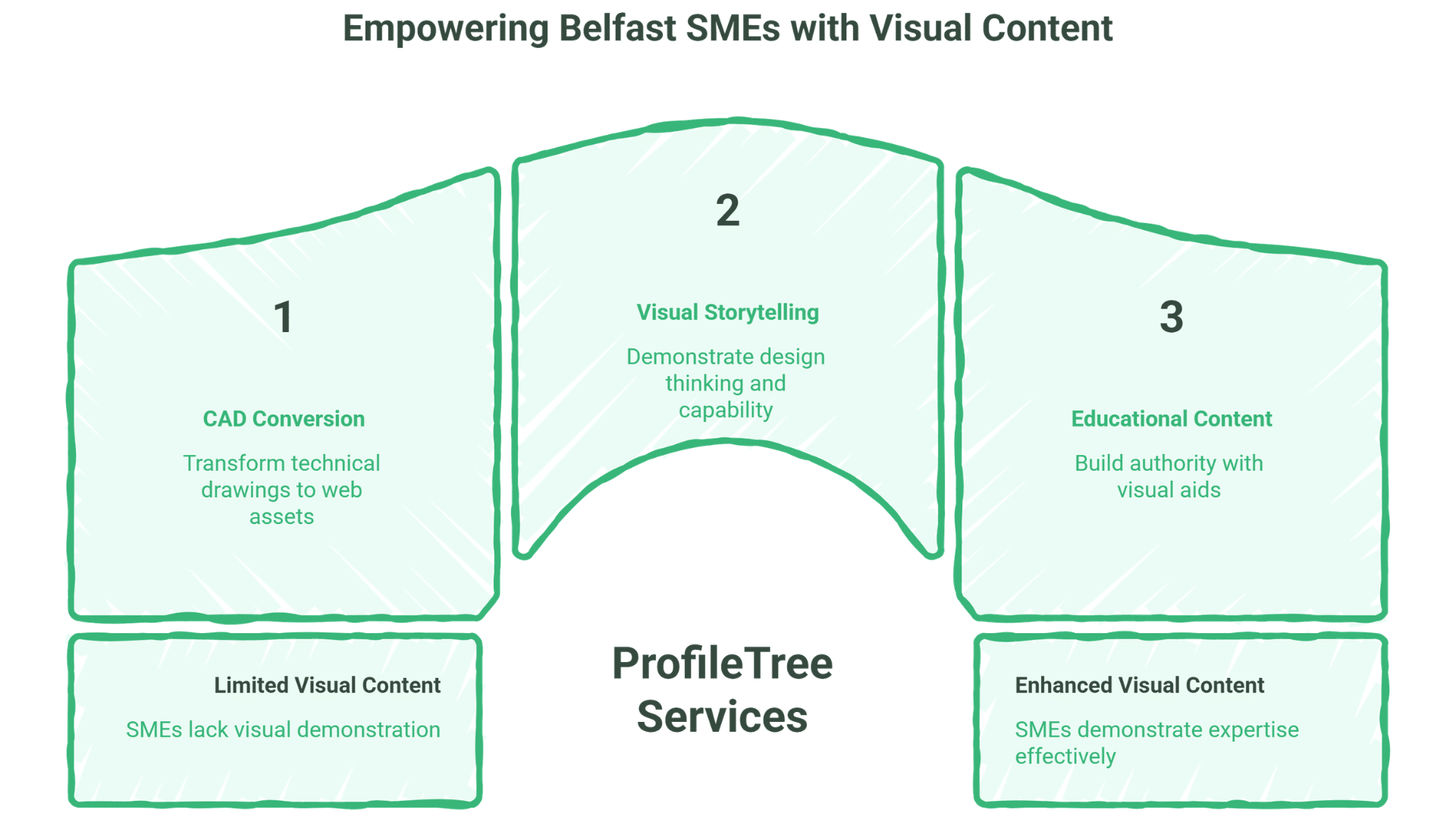
For Architecture & Construction
- If you have: Project portfolios currently shown as static images
- You need: Visual storytelling that demonstrates design thinking and technical capability
- ProfileTree approach: We combine architectural renders with video walk-throughs, technical explainer animations showing construction methods, and case study content that ranks for local search terms
Start small: Create one detailed case study with 3D visualisations, process explanation, and client testimonials. Use this as your template for future projects.
For Professional Services
- If you have: Technical expertise but no visual way to demonstrate it
- You need: Educational content and visual aids that build authority
- ProfileTree approach: Through our digital training services, we teach your team to create diagrams, flowcharts, and explainer content using accessible tools like Canva Pro and Figma
Start small: Document your most common client question as a visual guide. Publish it as a blog post with embedded diagrams. Monitor which searches bring visitors to this content.
Technical Drawing in Digital Marketing: Converting Assets to Leads
The convergence of technical drawing principles and digital marketing creates powerful opportunities for Northern Ireland businesses. Technical drawings excel at visually communicating how something functions, making them invaluable in marketing materials that need to explain complex products or services. The same precision and clarity that made Victorian engineering drawings effective communication tools now separates strong B2B marketing from generic stock photography.
Why Technical Content Builds B2B Trust
In expert-to-expert sales cycles, buyers want proof of capability, not lifestyle imagery. A detailed technical diagram, annotated CAD view or exploded assembly drawing signals expertise in ways that stock photography cannot replicate.
Belfast manufacturers competing for contracts with UK and European buyers often compete against lower-cost alternatives from Asia. Technical transparency—showing exactly how your products work, what materials you use and how you solve specific problems—justifies premium pricing and builds buyer confidence.
ProfileTree’s approach to web design for Belfast engineering firms prioritises this technical transparency. Rather than hiding complexity behind simplistic marketing messages, we make technical detail accessible through clear visual hierarchy, progressive disclosure, and intelligent information architecture.
The Trust Signals Comparison
| Content Type | Perceived Authenticity | Technical Detail | Buyer Confidence | Production Cost |
|---|---|---|---|---|
| Stock Photography | Low | None | Low | £10-50/image |
| Technical Illustrations | High | High | High | £200-500/image |
| Interactive 3D Models | Very High | Very High | Very High | £500-2,000/model |
| Technical Animation | Very High | Very High | Very High | £1,500-5,000/video |
The investment in proper technical visualisation pays back through shorter sales cycles and higher conversion rates. B2B buyers who engage with technical content are typically further along the buying journey and require less convincing.
Protecting Intellectual Property While Marketing
One concern we hear from Belfast manufacturers: “Won’t showing detailed technical drawings help competitors copy our designs?”
The solution is strategic redaction. Export simplified views that demonstrate capability without revealing proprietary dimensions, materials, or assembly methods. Show exploded views that illustrate how components fit together without revealing exact specifications. Create partial cross-sections that explain functionality without exposing complete internal mechanisms.
For products with registered designs or patents, technical marketing content can actually strengthen your IP position by establishing public documentation of your innovation timeline. Just ensure you’re showing what’s already public (through patent filings) or what’s protected, not revealing trade secrets.
Measuring ROI: How Technical Content Shortens Sales Cycles
“We’ve found that technical content doesn’t just attract more traffic; it attracts better-qualified traffic,” says Ciaran Connolly, founder of ProfileTree. “Belfast manufacturers who publish detailed technical guides and product specifications see reductions in unqualified enquiries. Visitors who’ve already studied your technical content arrive understanding what you do and why you’re different.”
For Northern Ireland businesses selling complex products or services, this filtering effect is valuable. Rather than spending sales time explaining basics, your technical content does that education work. Sales conversations start at a higher level, focused on specific applications and commercial terms.
The Technical Asset Matrix
Understanding which technical assets serve which marketing purposes helps prioritise conversion efforts:
| Original Format | Marketing Output | Best Platform | Typical Use Case |
|---|---|---|---|
| .DWG CAD file | SVG vector graphic | Website product pages | Dimensioned product diagrams |
| .STEP 3D model | GLB interactive viewer | Website, AR apps | Customer product configuration |
| .PDF blueprint | Annotated PNG | Case studies, LinkedIn | Project documentation |
| CAD animation | MP4 video | YouTube, website | Assembly/installation guides |
| Technical spec | Infographic | LinkedIn, blog posts | Educational content |
Each format serves a specific purpose in the buyer journey. Early-stage prospects benefit from high-level explainer videos. Late-stage prospects evaluating specifications need detailed dimensioned drawings and material certificates.
Contemporary Trends: AR, VR and the Future of Technical Visualisation
Modern CAD systems, now powered by artificial intelligence and machine learning, assist designers by suggesting optimisations and automating repetitive tasks. One of the most transformative tools in architecture and construction is Building Information Modelling (BIM), which allows multi-disciplinary teams to collaborate seamlessly on complex projects.
Beyond traditional CAD, advancements in augmented reality (AR) and virtual reality (VR) are adding new dimensions to technical drawing. Engineers and architects can now immerse themselves in 3D visualisations of their designs, identifying potential issues before construction begins.
For Belfast businesses, these technologies are becoming accessible:
Augmented Reality Product Viewers – Customers can use smartphones to view your products in their actual workspace before ordering. Industrial equipment suppliers can offer an AR preview of their machinery; buyers can see whether the equipment fits in their factory floor space before committing to purchase.
Virtual Showrooms – Architecture firms can give clients VR walk-throughs of designs before construction begins. This reduces revision cycles and builds confidence in the design process.
Digital Twins – Virtual replicas of physical assets are already bridging the gap between design and real-world operation, offering real-time data for monitoring, maintenance, and optimisation. While enterprise-level, this technology is becoming relevant for larger Belfast manufacturing operations.
Sustainability and Technical Documentation
Sustainability isn’t just a trend; it’s a regulatory requirement. Designers are increasingly called to create solutions that minimise environmental impact, and technical drawings play a role in documenting and proving environmental claims.
Sustainability tools integrated into CAD software enable designers to assess material efficiency and energy consumption throughout a product’s life cycle. For Northern Ireland manufacturers pursuing ESG objectives or targeting environmentally-conscious buyers, technical documentation that proves sustainability claims is increasingly valuable.
FAQs
What are technical drawings used for?
Technical drawings convey precise information about objects, structures, or systems. Acting as a universal language, they ensure clarity and consistency across engineering, architecture, manufacturing, and construction projects. For Belfast businesses, technical drawings serve dual purposes: guiding internal manufacturing and communicating capabilities to customers.
Are there different types of technical drawings?
Absolutely! Technical drawings vary based on industry and purpose. Common examples include architectural plans (for buildings and structures), mechanical blueprints (machine parts and assemblies), electrical schematics (circuit layouts and wiring), and civil engineering diagrams (roads, bridges, and infrastructure).
Why was drawing so important in early architecture?
Before the advent of sophisticated tools and software, drawing was the chief means of visualising and communicating complex designs. It enabled architects to plan proportions, estimate materials, and coordinate with builders, ensuring projects stayed aligned with the intended design.
How have advancements in technology impacted the creation and use of technical drawings?
Technological progress, from mechanical drafting machines to modern CAD and 3D modelling, has made technical drawings more precise, shareable, and modifiable. Today, designers can easily collaborate across the globe, simulating and refining concepts long before anything is built.
Can I use raw CAD files on my website?
No, raw CAD files (.dwg, .step, .iges) are too large for web use and often contain proprietary information. Convert to web-optimised formats instead: SVG for 2D diagrams, GLB/GLTF for interactive 3D viewers, or MP4 for animated demonstrations. ProfileTree’s web development services handle this conversion, ensuring technical accuracy whilst optimising for web performance.
How do I protect my patents when sharing technical drawings online?
Share partial views, exploded diagrams, and simplified schematics that demonstrate capability without revealing complete specifications. For patented designs, show only what’s already public in patent filings. For trade secrets, create “marketing-only” simplified versions that explain functionality without exposing proprietary methods. Our content marketing team helps Belfast manufacturers identify what to show and what to protect.
What approach replaced creating construction drawings by hand?
Computer-aided design (CAD) tools replaced manual drafting, allowing engineers and designers to create precise drawings on digital platforms. This shift accelerated design processes, reduced errors, and enabled easy modifications. Modern cloud-based CAD platforms now enable real-time collaboration across distributed teams.
Does using technical drawings help with SEO?
Yes, when properly implemented. Technical drawings should include descriptive alt text for accessibility and search indexing. Interactive 3D viewers increase dwell time, which Google interprets as a quality signal. Technical content that thoroughly answers buyer questions ranks for long-tail keywords that competitors miss. ProfileTree’s SEO services for Belfast businesses combine technical content with proper schema markup and internal linking strategies.
Should Belfast manufacturers invest in CAD training or outsource to agencies?
Both have value. Keep CAD expertise in-house for engineering work requiring precision and iterative design. Outsource marketing conversion (CAD to web-ready assets) and content creation to agencies with digital marketing expertise. ProfileTree’s digital training programmes can upskill your team in accessible design tools (Canva) for day-to-day marketing needs, whilst we handle complex 3D visualisation and website integration.
What’s the difference between technical illustration and graphic design?
Technical illustration prioritises accuracy and clarity, showing exactly how things work with precise dimensions and relationships, in contrast to artistic drawings, which focus on expression and aesthetic value rather than functional detail. Graphic design prioritises visual appeal and emotional impact, creating brand identity and marketing messages. B2B technical businesses need both: technical illustration for credibility, graphic design for memorability. The strongest marketing combines both disciplines.
Ready to Take Your Technical Drawing Skills to the Next Level?
The evolution of technical drawing from Leonardo da Vinci’s hand-drawn machines to modern CAD systems demonstrates humanity’s drive to transform abstract ideas into tangible designs. For Belfast businesses, this evolution continues; the principles remain constant, but the tools become increasingly accessible.
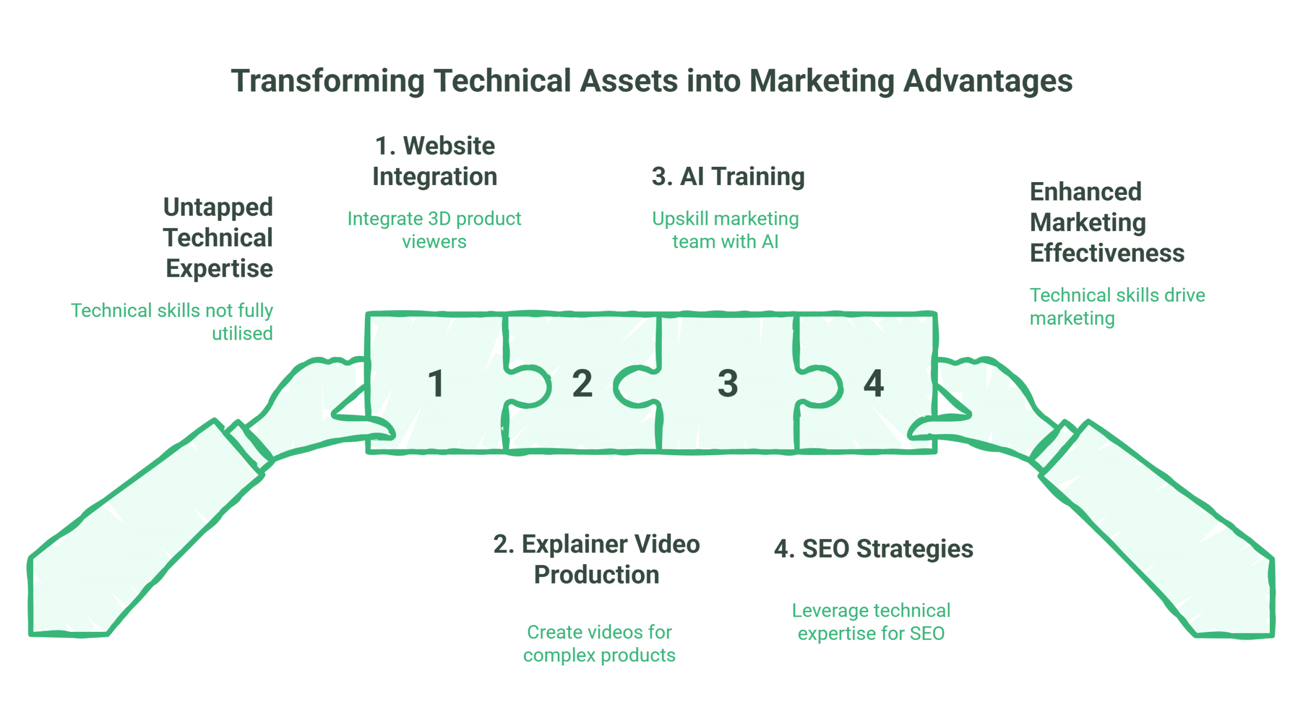
ProfileTree helps Northern Ireland SMEs bridge the gap between technical capability and digital marketing effectiveness. Whether you need website integration of 3D product viewers, explainer video production for complex products, AI training for your marketing team or SEO strategies that leverage your technical expertise, we apply the same precision-first approach that made Victorian engineering drawings effective.
Ready to transform your technical assets into marketing advantages? Explore our web design services for Belfast engineering firms, discover our video production capabilities, or enquire about digital training programmes that upskill your team in modern design tools.
The future of technical communication combines historical precision with modern accessibility. Your technical expertise deserves to be seen.
Technical drawing it is a tricky course with carelessness. You need discipline, commitment and consistent practice before you can bring the vest out of you.